What is a truth table?
The truth table is a table of inputs and outputs used in digital electronics. You usually start with a table of the outputs you want from the given inputs and design the circuit. This table is used to simplify Boolean equations obtained from digital circuits.
How many columns does a truth table have?
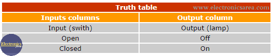
It can have many columns, but all tables operate in the same way. There is always at least one output column (on the right side) that represents the result of all possible combinations of the inputs.
The total number of columns in a truth table is the sum of inputs and outputs. The number of rows of the table is the number of combinations that can be achieved with the inputs, and it is equal to 2n, where “n” is the number of columns in the table (with no output columns)
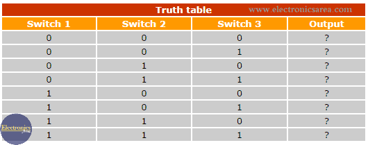
For example, in the following truth table, there are 3 input columns, so we will have 2³ = 8 combinations (8 rows). A circuit with three input switches (with 2 possible binary states: binary “0” or “1”) has 8 possible combinations. The output (exit column) is determined by the state of the input switches.
Logic circuits are basically an array of switches known as “logic gates” (AND gate, NAND, OR, NOR, NOT, etc.). Each of these logic gates has its own truth table.
If we could see in more detail the construction of these “logic gates,” we would realize that they are built with transistors, resistors, diodes, etc., and they are connected in a way that we obtain specific outputs for specific inputs.
The widespread use of logic gates simplifies the design and the analysis of complex circuits. Modern technology allows the construction of integrated circuits (ICs) that are composed of thousands (or millions) of logic gates.
Example of a 2 & 3 Input NOR gate Truth Tables
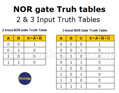
Analyzing the truth table of the 2-input NOR gate and the truth table of the 3-input NOR gate, we see that the outputs of the gates are “high” or “1” when their inputs are all “low” or “0.”
More Digital Tutorials
- What is the difference between Analog & Digital?
- What is a logic circuit?
- Digital logic levels (high, low, 1, 0)
- The truth table
- Boolean algebra
- Karnaugh Map (K-map)
- Binary number system
- Hexadecimal numbering system
- BCD code – binary coded decimal
- Gray code – Gray code table
- Aiken code – Excess 3 code
- AND gate
- NAND gate
- OR gate
- NOR gate
- NOT gate
- XOR gate
- How to build a NAND gate with transistors & diodes?
- OR & AND logic gates made with diodes
- The combinational circuit
- The sequential circuit
- JK Flip-Flop
- What is a binary decoder?


 - How to simplify Boolean functions")
