Home / Transformers /
The Power Transformer Structure
The power transformer structure is similar to that of a basic transformer. All electric power transformers, regardless of their size, have three fundamentals parts: High voltage winding, Low voltage winding and Core.
Power Transformer parts
– High voltage winding: It is an insulated coil of copper wire, with a low cross-section, built to receive or deliver the highest voltage of the electric power transformer.
– Low voltage winding: It is an insulated coil of copper wire, with a bigger cross-section, built to receive or deliver the lowest voltage of the electric transformer. When the electric power transformer is installed, the winding that is connected to the source is called primary winding and the winding that is connected to the load is called secondary winding.
– Core: The core is built with magnetic plates with a high proportion of silicon (4%); the core is also grain-oriented and has very low hysteresis losses. These plates have on one side an insulation that was impregnated in the metallurgical process.
Power Transformer core construction
There are two general constructions:
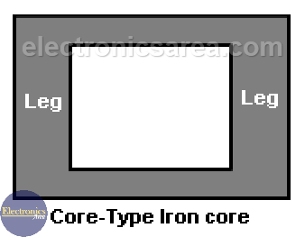
- The core-type construction.
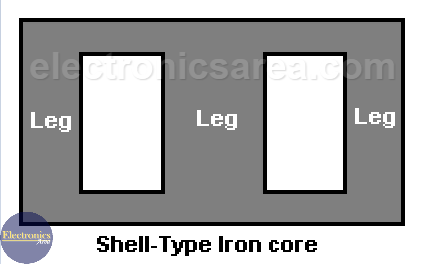
The windings are wrapped on each leg (primary and secondary). The magnetic flux flows through the legs. - The shell-type construction.
The center leg is twice the cross-section of either of the two outer legs. The magnetic flux is divided equally into two returning paths (the two outer core legs).
Core-type construction vs Shell-type construction
The Core-type construction option is less efficient than the Shell-type construction, because a small percentage of magnetic field lines flow out of the core. These are called “leakage flux”.
Power Transformer cooling
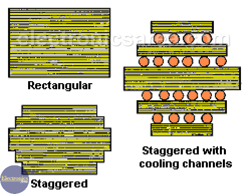
The rectangular legs are used in small transformers (up to 50KVA). In more powerful electric transformers, a staggered core section is used to increase the cooling surface. There are some special section core arrangement in order to avoid the overheating (look at the image below).
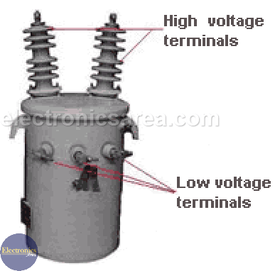
The picture right below shows the outer part of a common single phase transformer. On the picture there are the names of the different visible parts. Internally, there is the core, the primary and secondary windings with their respective terminals. All of this is submerged in a dielectric (electrical non-conductive) oil that serves as a cooler (heat sink).
More Transformer Tutorials
- Ideal Transformer Working Principle
- Transformer Turn Ratio (K)
- Impedance matching Transformer
- Autotransformer
- Transformer Structure
- Power Transformer usage
- Equivalent transformer circuits (power, audio, video and RF)
- Why is the core of a transformer laminated?
 - Power Factor Formulas")


