Home / Power Supplies /
Power Supply block Diagram
Many electronic circuits need a direct current (DC) voltage source, but what we commonly find are voltage sources of alternating current (AC). In order to achieve a direct current voltage source, the alternating current input must follow a conversion process like the one shown in the power supply block diagram below.
The image shows the main components of a basic power supply diagram and the waveforms at the beginning (AC input), at the end (DC output) and between blocks.
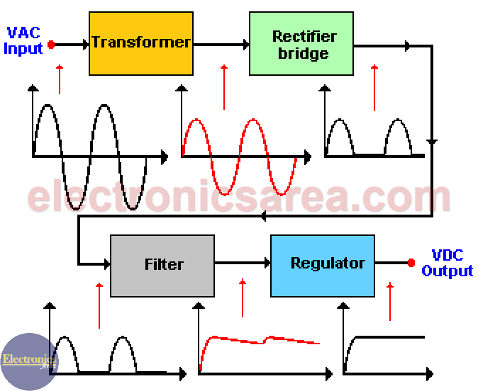
Input signal which goes to the transformer primary winding is a sine wave and its amplitude depends on the country’s electric distribution system (110/220 VAC or other). See the basic units of measurement in electronics.
Power Supply block diagram parts
Electrical Transformer
The electrical transformer receives on the primary winding an AC voltage and delivers on the secondary winding a different AC voltage (a lower one). This AC output voltage must be according to the DC voltage we want to obtain at the end.
For example: If we want a 12 VDC output, the secondary winding of the transformer must have an AC voltage no less of 9 volts.
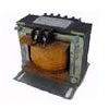
Electric transformer
The peak value at the transformer secondary winding is Vp = 1.41 x 9 = 12.69 volts. Even thought this value is very close to the one we wanted to get, it is not recommended because we need to take into account the voltage drops at different stages (blocks) of the power supply.
In this case, we can choose a transformer with a 12 volts AC secondary winding. With this AC voltage, we can get a peak voltage of: Vp = 12 x 1.41 = 16.92 volts.
Note: Vpeak = Vrms x 1.41
Rectifier bridge (rectifier diodes)
The rectifier bridge transforms the secondary winding AC voltage into a pulsating DC voltage. (look at the diagram). In our case, we use a ½ wave rectifier, then we eliminate the negative part of the wave.

Rectifier diode
Filter (capacitors)
Filter are one or more electrolytic capacitors in parallel that flattens or smooths the previous wave eliminating the alternating current (AC) component delivered by the rectifier.
These capacitors are charged to the maximum voltage value that the rectifier can deliver, and they are discharged when the pulsating signal disappears. Look at the picture above.
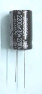
Electrolytic Capacitor
Voltage regulator
The voltage regulator receives the signal from the filter and delivers a constant voltage (let’s say 12 DC volts) regardless of the variations on the load or the voltage supply.
A voltage regulator can be implemented in several ways. It can be a transistorized voltage regulator or a monolithic voltage regulator.
The image below shows the LM7805 voltage regulator (5VDC output). You can also find the LM7812 voltage regulator (12VDC output).
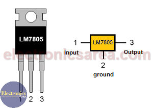
LM7805 Voltage regulator
Some circuit diagrams of variable power supply that may interest you:
- A small transistorized variable power supply circuit or a 12Volts 1 A power supply using a zener diode, useful for a 1 to 1.6 A maximum.
- If you deed more power, the 5 A variable power supply using the LM338 regulator or the 4A variable power supply with 4 LM317 regulators or an LM350 Voltage Regulator Adjustable P.S.
- A more powerful P.S. circuit diagram: The 20 A variable Power Supply with LM317.
Some circuit diagrams of fixed power supply that may interest you:
- If you need a fixed 12V PS, a 12V Power Supply using Zener and 741 Operational Amplifier or a 12V Power Supply using the 7805 are good choices.
- If you need a different output voltage, a 9V P.S. using Zener and Transistor.