OR and AND logic gates made with diodes
If we need a OR gate we can use a 4071 OR CMOS IC or a TTL 7432 OR IC. If we need a AND gate we can use a 4081 AND CMOS IC or a TTL 7408 AND IC, but sometimes it is easier to use diodes. Diode Logic uses the fact that diodes conduct only in one direction. (they behave like switches). It is recommended first to read: Logic Levels.
Diode Logic OR gate (wired OR connection)
If one or both inputs are at logic “1” (5 volts), the current will flow through one or both diodes. This current passes through the resistor and causes the appearance of a voltage across its terminals, thereby obtaining a logic “1” on the output.
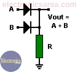
We only get logic “0” (0 volts) on the output when both inputs are in logic “0”. In this case, the diodes do not conduct, there is no current through the resistor R and there is no voltage across its terminals. As a result, the voltage at Vout is the same as ground (0 volts)
Diode Logic AND gate (wired AND connection)
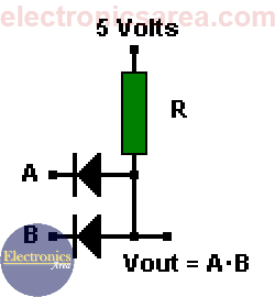
When both inputs are at logic “1″, the two diodes are reverse biased and there is no current flowing to ground. Therefore, the output is logic “1” because there is no voltage drop across the resistor R.
If one of the inputs is logic “0”, the current will flow through the corresponding diode and through the resistor. Thus the diode anode (the output) will be logic “0”.
This method works fine when the circuits are simple, but there are problems when you have to make interconnections with such gates.
Interconnecting OR & AND gates
We make a connection of 2 AND gates and 1 OR, as shown on the picture.
If we analyze carefully the picture, we notice that one of the two AND gates outputs will be in logical “1” (high level), when the A and B inputs or the C and D inputs are in logical “1” (high level).
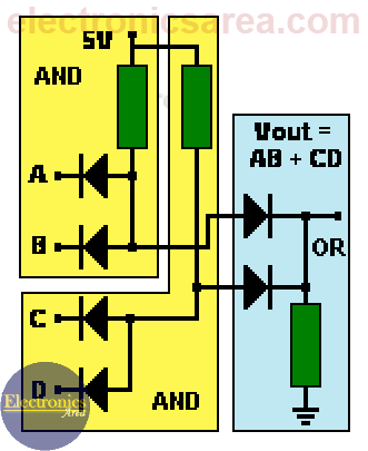
These outputs serve as inputs for the OR gate.
Analyzing the output of the OR gate and assuming that the values of the resistors are the same throughout the circuit, a voltage division has been created, then the output voltage will be approximately: Vout = (+V – Vd)/2.
By replacing V and Vd with real values on the last formula, we get: Vout = (5-0.7)/2 = 2.15 Volts. (We divide it by 2 because there are two resistors of equal value on the electric current flow)
In the case in which all inputs (A, B, C, D) are on logical “1”, the two resistors of the AND gates would be in parallel, and they would be in series with the OR gate resistor. This would provide an output voltage of 2.85 Volts. This level is in the not allowed (prohibited) area for a logical “1”.
If we put more gates in cascade the problem will be more serious, so this method is only used for simple gates.
Note: Vd = Diode voltage drop = 0.7 volts.
More Digital Tutorials
- What is the difference between Analog & Digital?
- What is a logic circuit?
- Digital logic levels (high, low, 1, 0)
- The truth table
- Boolean algebra
- Karnaugh Map (K-map)
- Binary number system
- Hexadecimal numbering system
- BCD code – binary coded decimal
- Gray code – Gray code table
- Aiken code – Excess 3 code
- AND gate
- NAND gate
- OR gate
- NOR gate
- NOT gate
- XOR gate
- How to build a NAND gate with transistors & diodes?
- OR & AND logic gates made with diodes
- The combinational circuit
- The sequential circuit
- JK Flip-Flop
- What is a binary decoder?


Why there is no Vcc(+5v d.c supply) in case of diode equivalent circuit of OR gate?
Hello
There is no need for a 5 volt voltage source. When the input signals (A or B) are a logical “1”, they have a voltage of 5 volts which, when passed through the diode, appear at the output. Vout = (A + B).
Regards
I think this is a real great blog post. Much thanks again.
very good
Thank you Shailesh!