Home / Semiconductors /
Darlington transistor
The Darlington transistor is a special type of transistor with a high current gain. It consists of two internally bipolar transistors being connected in cascade, as shown in the following image.
How a Darlington transistor work?
Analyzing the following image, it is seen that transistor T1 gives the current that comes out of its emitter to the base of transistor T2. The current gain equation of a typical transistor is: IE = ßxIB (collector current is equal to beta times the base current).
The image shows a Darlington transistor with its pin configuration and its internal structure. We know that:
- On the first transistor: IE1 = ß1 x IB1. Equation (1).
- On the second transistor is: IE2 = ß2 x IB2. Equation (2).
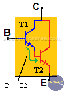
From the image, we see that the emitter current of the T1 transistor is the same as the base current of the T2 transistor. Then IE1 = IB2. Equation (3).
Using the equation (2) and the equation (3) we obtain: IE2 = ß2 x IB2 = ß2 x IE1.
Replacing the value of IE1 on the last equation (see equation (1)) we obtain the Darlington transistor gain equation: IE2 = ß2 x ß1 x IB1.
Darlington Current Gain
From the Darlington transistor gain equation: IE2 = ß2 x ß1 x IB1, we can see that the current gain is much greater than the one of a single transistor, since it takes advantage of the current gain of the two transistors. (The gains are multiplied).
For example:
If we have two transistors with gain of 100 each (ß = 100), connected as a Darlington transistor using the above formula, the final theoretical gain would be: ß2 x ß1 = 100 x 100 = 10000.
This seems to be a very big gain (the ideal one) but it is actually a lower gain. Darlington transistors are widely used in circuits where it is necessary to control large loads with very small currents.
Very important: When we add the base-emiter voltage of the first transistor B1 to E1 (0.7 volts) plus the base-emitter voltage of the second transistor B2 to E2 (0.7 volts), we get as a result a voltage drop of 1.4 volts between the base and the emitter of the Darlington transistor. VB1E1 + VB2E2 = 0.7 + 0.7 = 1.4 volts.


")