Home / Circuits / LED Circuits /
Light-Emitting diode connected to 120/240 VAC
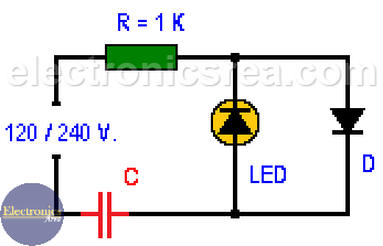
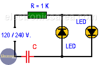
This circuit shows one or two LEDs (Light-Emitting Diode) directly connected to the outlet (120 VAC or 240 VAC). The reduction of the AC input voltage to one that is suitable to use in a LED diode is achieved using a capacitor and a resistor.
Caution: This circuit is connected directly to the power line (120 / 240 volts AC), so you must take special care to test it.
When two Light-Emitting Diodes are connected, the first LED diode will conduct in the negative semi cycle of the wave and the second one will conduct in the positive semi cycle of the wave. If you want to connect only one LED diode, you must replace the other one with a common rectifier diode. If this is not done, the LED will be burned.
The formulas we use are:
- Xc = 1/(2 p f C). Capacitive reactance formula.
- I = V/Xc. Ohm’s Law for the capacitive reactance.
Where:
- p = (π) 3.1416
- f = frequency (50 or 60 hertz)
- C = capacitor value (farads)
- V = voltage
- I = current
- Xc = capacitive reactance
LED diode connected to 110/120 Volts, 60 Hertz
- Xc = 1/(2 p f C) = 1 / (2 x 3.1416 x 60 x 0.47uF) = 5646 ohms
- I = V/Xc = 120/5646 = 21.3mA
With a 0.47uF non-polar capacitor the reactance will be 5646 ohms, and the current through the LED (or LEDs) will be 21.3mA (milliamps).
LED diode connected to 220/240 Volts, 50 Hertz
- Xc = 1/(2 p f C) = 1 / (2 x 3.1416 x 50 x 0.22uF) = 14.468 ohms
- I = V/Xc = 240/14.468 = 16.6mA
With a 0.22uF non-polar capacitor the reactance is 14.468 ohms, and the current through the LED (or LEDs) is 16mA (milliamps).
Note: The 1 Kilohm resistor is used to avoid possible current peaks, and its effect is negligible as most of the voltage drop is in the capacitor.
List of components
- 1 x 1K resistor (0.5 watts)
- 1 x 0.47uF non-polar capacitor, 200 volts or more for the 100/120 VAC case.
- 1 x 0.22uF non-polar capacitor, 300 volts or more for the 220/240 VAC case.
- 2 x LEDs
- 1 x 1N4001 rectifier diode
More LED circuits
- Emergency lighting circuit with LEDs
- Automatic night light circuit with one LED (PCB)
- Bike flashing LED lights circuit
- Flashing LEDs circuit for pedestrians
- Two-way traffic light circuit
- LED sequencer using 4017 decade Counter (LED Chaser)
- Light push button circuit with time delay
- Energy-saving flashing pilot light
- LED connected to 120/240 VAC
- Police style strobe light circuit


")