What is a Logic AND Gate?
The logical AND gate is one of the simplest gates in digital electronics. The symbols for a 2-input and a 3-input AND gate and truth tables are shown in the following figure. The output of an AND gate is true (“1”) only if all inputs are true (“1”). If one or more inputs are false (“0”), the output is false (“0”).
2-input & 3-input AND truth tables
The first illustration shows the symbol of a 2-input AND gate, and the second illustration shows the symbol of a 3-input AND gate.
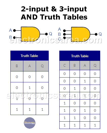
2-input & 3-input AND truth tables
The 2-input AND logic gate is the most common, although it can have many more inputs (A, B, C, etc.), but it has only one output: Q. The 2-input and 3-input AND gates have the above truth tables.
It is easy to see that output Q is “1” (true) when inputs A and B are both “1”. In other words, output Q is “1” when inputs A and B are “1”. The AND gate is represented by Boolean algebra as Q = A*B or Q = AB. A 3-input AND logic gate implemented with switches is shown in the following figure.
How to make a logical AND gate implemented with switches?
To implement an AND logic function using switches, they are connected in series. If all switches are closed, the lamp turns on (true / “1”). If one more switch is open, the lamp turns off (false / “0”).
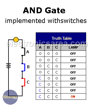
Truth table of a 3 switch AND logic gate. O = open and C = closed.
The switches are A, B, and C.
You may also like to how to make an AND gate with diodes
The AND gate can have many inputs. We can create a multi-input AND gate by connecting 2-input AND gates in cascade. The problem with cascading AND gates is that it increases the propagation delay (the time it takes for the signal to travel from the input to the output).
How to Build a 3 Input Logic AND Gate with 2 Input AND Gates
We can build a 3-input AND gate by cascading 2-input AND gates. This is shown in the figure below.
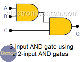
The truth table is similar to the one shown above where switches are used. Using the same method, we can implement a logic AND gate with 4 or more inputs.
Multi-input AND gate
A 6-input AND gate can be constructed using the following schematic:
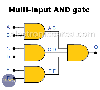
This diagram uses one 3-input AND gate and three 2-input AND gates.
You can easily get a NAND gate by concatenating an AND gate with an inverter gate (NOT gate), or vice versa, you can get an AND gate by concatenating a NAND gate with a NOT gate, but there are other logic gates such as the OR gate, the NOR gate, and the XOR gate that are needed to create digital circuits.
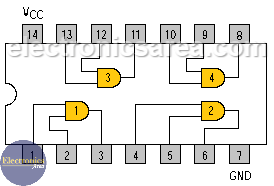
The TTL 7408 Quad 2 input AND Gate Pinout
More Digital Tutorials
- What is the difference between Analog & Digital?
- What is a logic circuit?
- Digital logic levels (high, low, 1, 0)
- The truth table
- Boolean algebra
- Karnaugh Map (K-map)
- Binary number system
- Hexadecimal numbering system
- BCD code – binary coded decimal
- Gray code – Gray code table
- Aiken code – Excess 3 code
- AND gate
- NAND gate
- OR gate
- NOR gate
- NOT gate
- XOR gate
- How to build a NAND gate with transistors & diodes?
- OR & AND logic gates made with diodes
- The combinational circuit
- The sequential circuit
- JK Flip-Flop
- What is a binary decoder?


